DRO-350 Add-ons
Tachometer
The DRO-350 auxiliary port provides for the connection of a tachometer to measure rotational speed. The tachometer is displayed on the Z2 axis in RPM or in SFM, which for lathe operations is based on the reading of the X axis and for mill operations is based on the tool diameter. There are a lot of possibilities for the design of the tachometer. Two versions will be presented here as examples, one based on a reflective sensor and one based on a photo-interrupter sensor. Many other designs are possible so long as the auxiliary port receives one 5V pulse per revolution.
Reflective Tachometer
A reflective tachometer senses the rotational speed based on light and dark areas on the rotating object and does not require anything to be mounted to the object. It is thus easy to install but can be a little bit tricky to calibrate. The light and dark areas are made by placing a piece of black electrical tape on the rotating object or by using a black magic marker such as a Sharpie to color a dark area. Cleaning and polishing the rotating object will help increase the contrast between dark and light and will make the tachometer easier to calibrate.
The reflective tachometer presented here is based on the Fairchild QRB1114. It works by shining an infrared LED on the rotating object and "seeing" the reflection with a phototransistor. The QRB114 is a popular part but there are several other reflective sensors that could be used in its place. The infrared LED is current limited to about 17mA by resistor R1. The sensitivity of the phototransistor is set by resistor R2. The value of R2 is directly proportional to the sensitivity of the phototransistor, increasing R2 increases the phototransitor's sensitivity and vice versa. Start with a value of 4.7K and adjust depending on ambient light and the amount of reflection provided by the rotating object.
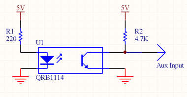
Reflective Tachometer Schematic
Auxiliary Cable Plug Signals
The reflective tachometer is built by mounting the QRB1114 to a small piece of perf-board. The resistors are then soldered to the appropriate pins on the QRB1114. The perf-board is connected to a three conductor cable carrying 5V, ground, and the tachometer input. To prevent swarf and coolant from getting onto the circuit end of the cable and shorting something out, the circuit can be sealed with hot glue.
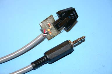
Construction of Reflective Tachometer Circuit
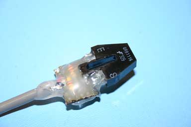
Reflective Tachometer Circuit Sealed in Hot Glue
Mounting the tachometer cable on a mill or lathe is highly dependent on the machine itself. Below is shown an example mounting on a mini-mill like those sold by Harbor Freight, Grizzly, Homier,etc. A small bracket is machined with a raised area to mount the sensor on. The raised area is tapped for a 4-40 screw that will fit through the slit in the sensor to mount it to the bracket. The bracket is mounted to the mill by drilling a clearance hole in the bracket and using one of the three metric cap screws attached to the bottom of the mini-mill near the spindle.
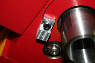
Mounting Bracket for the Reflective Tachometer Sensor
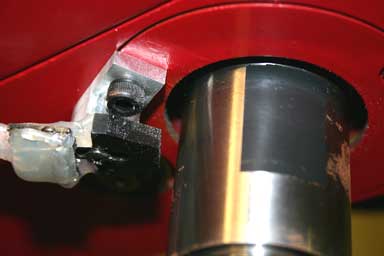
Reflective Tachometer Sensor Mounted to the Bracket
Calibrating the sensor will take a little trial and error to get the best possible voltage differential between light and dark. Start by putting the shiny side of the rotating object towards the sensor. Use a voltmeter to measure the voltage output from the sensor. Slide the sensor closer and farther away until you find the lowest possible voltage reading. Moving the sensor slightly from side to side will also affect the reading. The voltage level should be lower than about 1.5VDC for reliable operation.
Turn the rotating object until the dark region is facing the sensor. The voltage level should be greater than about 3.5VDC for reliable operation. If you can't get enough voltage differential or you can't get below 1.5VDC or above 3.5VDC, then you may need to try a different resistor value for R2.
If you get false or multiple triggers from the sensor while operating the tachometer, then you may need to put a capacitor on the auxiliary input from the sensor to provide some transient filtering. Start with a value of around 1 uF and determine the best value experimentally.
Interrupter Tachometer
An interrupter tachometer senses the rotational speed on an object by having a part of the object pass in front of an infrared LED. Usually, the interrupter wheel is directly attached to the object to be measured. Interrupter wheels have a certain number of teeth like a gear where the number of teeth is dependent on the tachometer design. For the design presented here, an interrupter with a single tooth is required since the DRO-350 expects one 5V pulse per revolution.

Interrupter Wheel for use with the DRO-350
The interrupter tachometer design is based on the Sharp GP1S53V photointerrupter. There are a multitude of photointerrupters that will work in its place with the same resistor values so use whatever sensor you prefer. The infrared LED is current limited to about 17mA by resistor R1. The sensitivity of the phototransistor is set by resistor R2. The value of R2 is directly proportional to the sensitivity of the phototransistor, increasing R2 increases the phototransitor's sensitivity and vice versa.
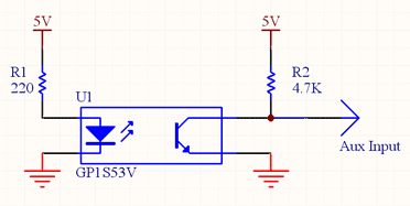
Interrupter Tachometer Schematic
The interrupter tachometer circuit can be built on a small piece of perf-board. The choice of construction technique will depend on how you mount the sensor to the lathe or mill. The resistors are soldered to the appropriate pins on the GP1S53V and a three conductor cable is soldered in place to provide the connections to the DRO-350.
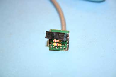
Interrupter Tachometer Sensor Circuit