DRO-350 Add-ons
Electronic Edge Finder
The DRO-350 supports an electronic edge finder via its auxiliary input. The electronic edge finder allows for rapid setup by simply having to touch the work piece to register the position in the DRO-350. The Enco Machinst's Mate is recommended as an affordable electronic edge finder but many other edge finders will work equally as well here. Two ways are presented here to connect the electronic edge finder to the DRO-350. The first way requires minor modifications to the edge finder to electrically couple it to the DRO-350. The second way uses the edge finder as is and instead optically couples it to the DRO-350.
Direct-Coupled Edge Finder
The design for the direct-coupled edge finder works by replacing the light bulb with two wires that connect directly to the edge finder, one wire to the negative battery terminal and the other to the probe. A general purpose NPN transistor translates the 1.5V signal from the battery to a 5V signal as required by the DRO-350. When the probe touches the object, the switch representing the probe is closed which will bias the NPN transistor on via the 100K base resistor. The NPN transistor is in a common emitter configuration with a 10K collector resistor.
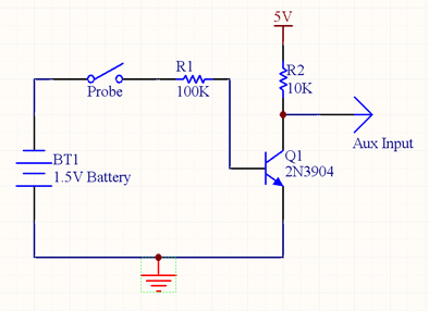
Direct-Coupled Edge Finder Cable Schematic
The edge finder circuit is built by first disassembling the edge finder. Remove and place aside the light bulb that is contained inside. Make a small adapter out of a wooden dowel that is the same height as the light bulb. Attach a wire to both ends of the dowel with small wood screws.
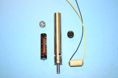
Disassembled Electronic Edge Finder
Feed the two wires from the dowel down the shaft of the edge finder and poke them out one of the holes at the probe end. Slide the dowel down after the wires making sure to keep the wires out of the way. Replace the battery inside of the edge finder with the negative end towards the top of the dowel. Put the small spring on top of the battery and close the edge finder with the screw. With an ohmmeter, make sure that the bottom wire is connected to the probe and that the top wire is contacting the negative side of the battery.
Construct the transistor circuit to the end of the two wires coming out of the edge finder. You may want to use heat shrink tubing over the two wires to protect them before starting on the circuit. Solder the 2N3906, and the 10K and 100K resistors to the wires as shown in the schematic. Solder a three conductor cable to the circuit as indicated.
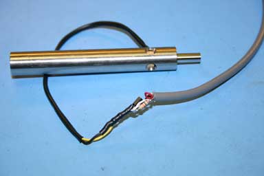
Construction of Direct-Coupled Edge Finder Circuit
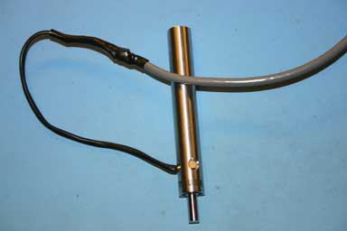
If a 5V supply is available, it would be a good idea to test the circuit at this point. Connect the 5V supply and its ground to the appropriate wires on the cable. Connect a voltmeter to the wire on the cable that is connected to the auxiliary input and make sure that it reads 5VDC. Short the edge finder probe to the body and make sure that the auxiliary input drops to 0VDC. Assuming that no problems are found in the circuit, seal the circuit with a piece of heat shrink tubing to protect it.
Tachometer Cable Sensor Mounted to the Bracket
Optically-Coupled Edge Finder
The optically-coupled edge finder design does not require any modifications to the edge finder. It works by using a phototransistor to switch the auxiliary input to ground when it sees the light from the edge finder. The circuit uses a Sharp PT4800 NPN phototransistor. The most important attribute for the phototransistor is that it must be sensitive to visible light. Many phototransistors are designed to be used in infrared applications and have a visible light filter to minimize interference. These types of phototransistors will not work as well or at all with this application. Otherwise, the choice of phototransistor is not that important and most generic types will work fine.
The circuit uses a single resistor on the collector to set the phototransistor's sensitivity. The value of this resistor can be determined experimentally or you can use a potentiometer to allow for some flexibility after installation. Typically, the best resistor value is between 5K and 15K for most generic phototransistors.
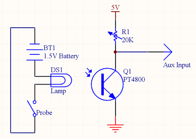
Optically-Coupled Edge Finder Schematic
The construction of the circuit is very straightforward with only two components. Solder the phototransistor to the resistor or to the potentiometer, if preferred. Connect a three conductor cable to the appropriate places as shown in the schematic. The circuit should be protected with heat shrink tubing to make sure that nothing is shorted out during use.
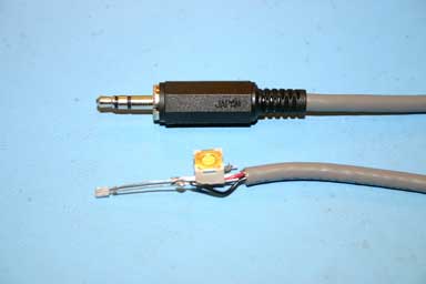
Construction of Optically-Coupled Edge Finder Circuit
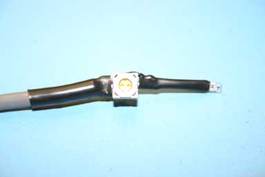
Circuit Protected with Heat Shrink Tubing
It is important to minimize the amount of ambient light seen by the sensor. This maximizes the light and dark regions for the phototransistor and will make it more reliable and easier to calibrate. In the following photo, electrical tape is used to attach the sensor to the edge finder. Other mounting methods can be used so long as the sensor is kept dark.
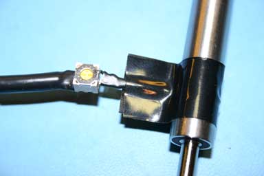
Sensor Connected to the Edge Finder with Electrical Tape