DRO-550 PCB Construction
Step 3. Electrical Test
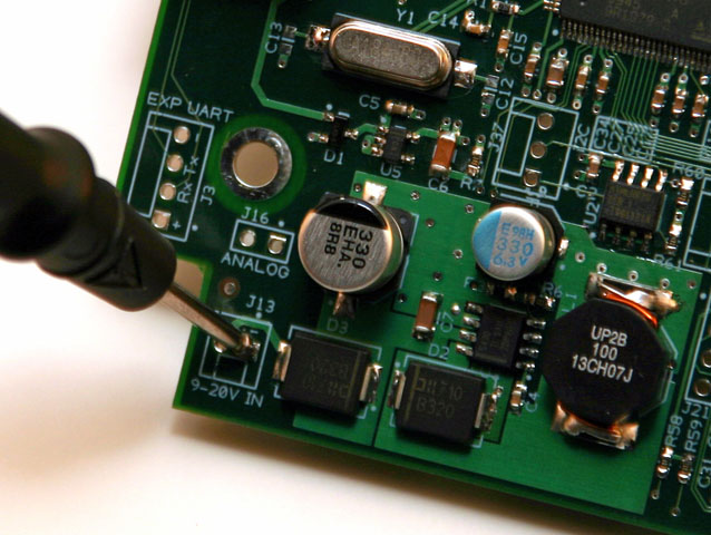
Ground Probe Point
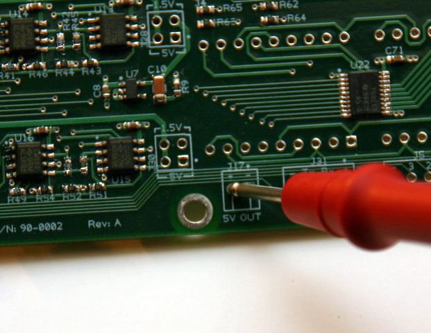
5V Probe Point
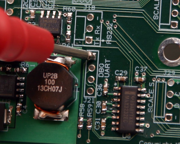
3.3V Probe Point
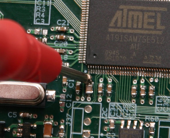
1.8V Probe Point
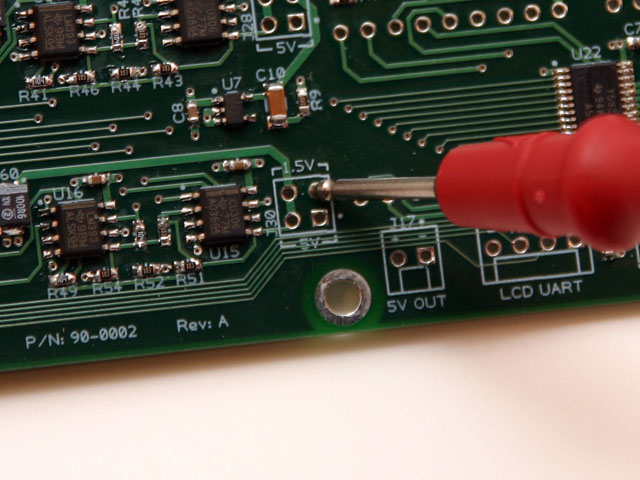
1.5V Probe Point
The DRO-550 circuit board contains five power planes: ground, 5V, 3.3V, 1.8V and 1.5V. The board is constructed out of four layers with the power planes existing on the two internal layers. Since there is no way to directly inspect these layers, we will electrically check them for shorts using 5 test points.
Get your multimeter and set it to measure resistance. The table below lists the ten possible combinations of the five power planes. We will measure the resistance between each possible combination using the multimeter. For each combination, verify that the resistance is greater than 1K ohm.
Reference the pictures to the left that show convenient test points for each of the five planes. The ground test point is the square pad ("-" label) on the J13 header ("9-20V IN" label). The 5V test point is the round pad ("+" label) on the J17 header ("5V OUT" label). The 3.3V test point is the square pad on op of the J21 header ("DBG UART" label). The 1.8V test point is a little bit harder to probe than the rest since you will need to probe at the top of the C27 capacitor located to the lower left of the processor. It is the one that is slightly larger than the ones directly beside it. You can probe either directly on the shiny part of the capacitor or on the small round via directly above it. The 1.5V test point is the upper-right, round pad on the J30 header. The pad is directly below the "V" in the "-1.5V-" label.
| Black Probe |
Red Probe |
| Ground | 5V |
| Ground | 3.3V |
| Ground | 1.8V |
| Ground | 1.5V |
| 5V | 3.3V |
| 5V | 1.8V |
| 5V | 1.5V |
| 3.3V | 1.8V |
| 3.3V | 1.5V |
| 1.8V | 1.5V |