DRO-550 PCB Construction
Step 4. Smoke Test
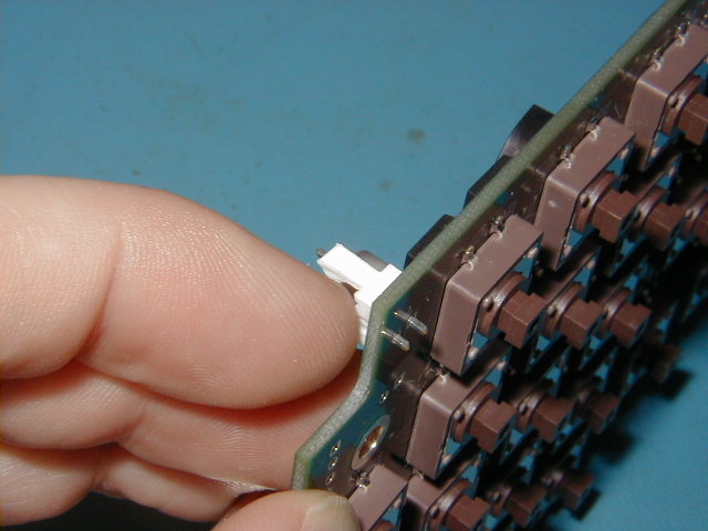
The smoke test is so named because if any of the magic electronic smoke is going to be released, then this is the time. In industry terms, a smoke test is the first time an electronic device is powered on. Before we can proceed, we must do a little soldering. Warm up your soldering iron and get your solder out. Take one of the white, 2-pin headers and place it in the J13 position in the lower left-hand side of the board. Make sure the vertical clip is facing to the outside edge of the board. Now, apply a little blob of solder to the tip of your soldering iron. With the tip of your finger, hold the header in position as shown in the photo at left. If you have some flux, apply it to the pins since the solder blob on your iron has burned away the flux in the solder. If you don't have flux, then don't worry about it, we can make do. Touch the solder blob to the base of the pin away from your finger so you don't burn yourself. The solder should flow both on the pin and the pad on the board so that it locks the header in place. Once it is held, then you can lay the board down and solder the other pin more carefully. It's a good idea to back the first pin and clean up the solder connection since they are often poor when soldered without flux. You can use solder wick to remove any excess solder.
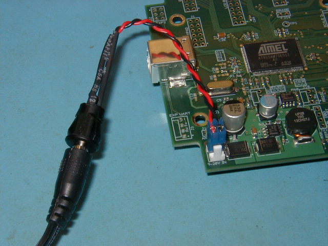
Retrieve the power supply that you are going to use for the DRO-550. It should be between 9 to 20 VDC and be rated for at least 1A. Look at the DRO-550 Hardware Manual for more information on power supply selection. The internal power cable has a female 2.1mm connector on one end and a 2-pin plug on the other. These can either be purchased or made yourself.
Plug the power supply into the internal power cable but leave the AC side UNPLUGGED. Connect the internal power cable onto the J13 header you just soldered in. With the board in front of you, plug the AC into the wall and look and smell for signs of overheating. If you notice any, IMMEDIATELY unplug the AC from the wall and seek assistance. If everything looks (and smells) good, then we can proceed on to checking the voltage levels.
Grab your multimeter and select the DC voltage measurement. We use the same test points as the ones we used for the electrical test in the previous step. Refer back to that page if you don't remember their exact locations. The four measurements we make are shown in the table below. The black probe from your multimeter should always be in the ground test point. Move the red probe to each of the four test points and verify that they are in the range shown below. BE VERY CAREFUL WHEN PROBING!!! This is a live board and a slip of the probe tip can short something out and potentially damage the board. If all of the voltages check out, then disconnect the power supply and we can move on. If any measurements don't check out, then double check your probe positions and if it is still out of range, then seek assistance.
| Black Probe |
Red Probe |
Measurement |
| Ground | 5V | 4.75V - 5.25V |
| Ground | 3.3V | 3.1V - 3.5V |
| Ground | 1.8V | 1.7V - 1.9V |
| Ground | 1.5V | 1.4V - 1.6V |