DRO-550 PCB Construction
Step 6. Solder Headers
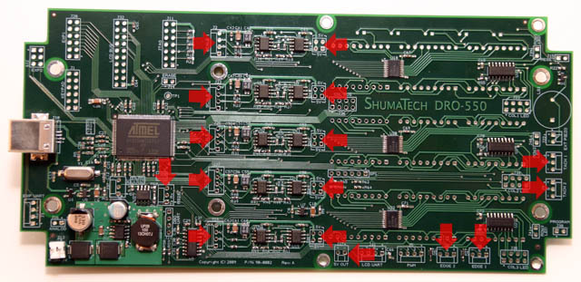
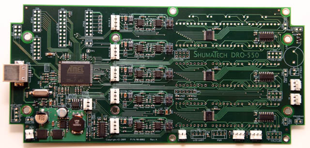
There are a number of through hole headers that we must solder onto the board: five 2x2 pin headers, five 4 pin headers, five 3 pin headers, and two 2 pin headers. We already soldered one of the 2 pin headers in place at J13 during the smoke test in step 4. Look at the picture at left for the locations for each of the headers. Use the same technique as before where you hold the header in place with one hand while applying a small blob of solder with the soldering iron in the other. Solder the remaining pins and clean up the first pins as before. Not that the pins on some of the headers are close to the keypad switches so you'll have to be a little careful. Don't worry if you end up scorching one since it is very unlikely that you damaged anything - just sit back and enjoy the delicate aroma of burnt plastic.
The rest of the headers are either for troubleshooting the board or for future expansion of the DRO-550's functionality. You can solder these additional headers on later when you need them.