DRO-550 PCB Construction
Step 8. Solder Piezo and Program Switch
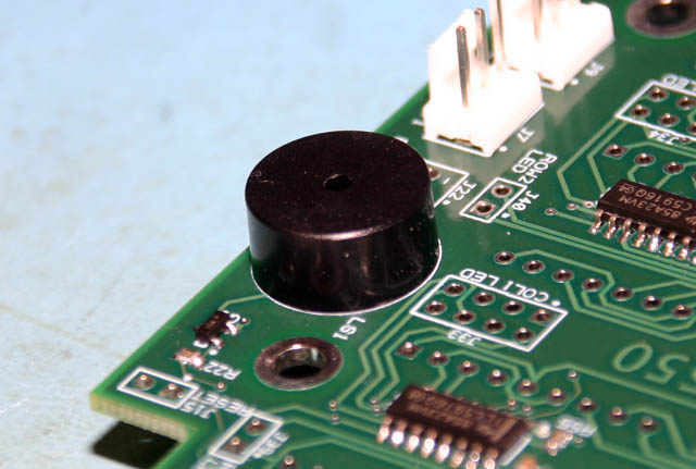
Solder the piezo buzzer into position onto the side of the board. There is room to solder it either on the component side or the display side of the board. A little experimentation might be necessary to refine the volume to your liking. You can also partially cover the small hole on top with tape to make it quieter.
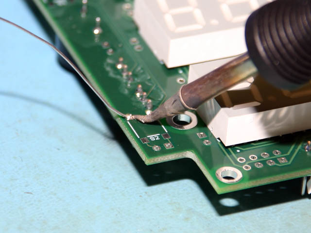
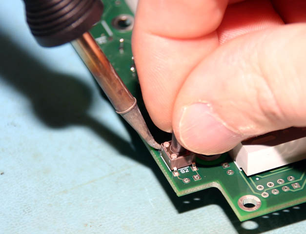
The program switch is a 6mm, surface mount tach switch. It is used as a last resort to place the DRO-550 intro program mode. Most of the time, you will use the OpenDRO menu interface to enter program mode and the program switch is not used. Since the switch is surface mount, a slightly different technique is required from the other through hole parts. Notice that there are four shiny pads for the switch with a white square in the middle that shows the proper position of the switch. Apply a little pool of solder to the upper left-hand pad. With your solder iron in one hand and holding the switch in the other hand, place the switch within the white box while heating the pool of solder you previously applied. Remove the iron and wait a second before releasing the switch to let the solder set. Inspect the position of the switch and make sure it is within the white box and that the other three pins are over their pads. If it's not quite right, then just apply the soldering iron to the pad again and reposition the switch. Once it is in place, solder the remaining three pads.