DRO-350 Enclosure Construction
Step 4. Install the Connectors
The three scale connectors are 4 pin mini-DIN type that mount to the back panel with six 4-40 x 1/2" black machine screws. The connectors listed in the bill of materials have a hole on either side that must be tapped 4-40 before mounting with the screws. This is most easily done with a small hand tap.
After tapping, mount the three scale connectors to the back panel with the 4-40 x 1/2" screws.
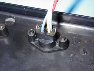
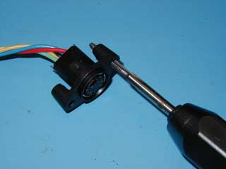
The auxiliary connector is a 3.5mm stereo jack Remove the nut included with the connector and mount it on the back panel. If the optional MTA connector is used, it must not be installed until after the stereo jack is installed because the MTA connector will not fit through the hole for the stero jack. Solder the wires to the stereo jack as shown in the auxiliary cable section.
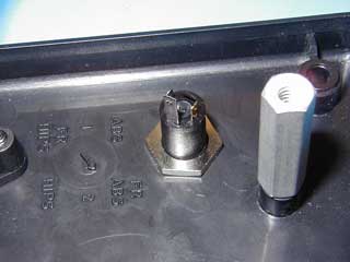
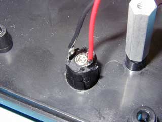
The DC power connector is a standard 2.1mm type. The connector listed in the bill of materials is a snap-in type that is simply pushed into the hole drilled into the back panel. Depending on the tolerances of the hole, you may need to put a few drops of hot glue or epoxy to assure that the connector does not pull out of the hole when the power cord is removed.