DRO-350 PCB Construction
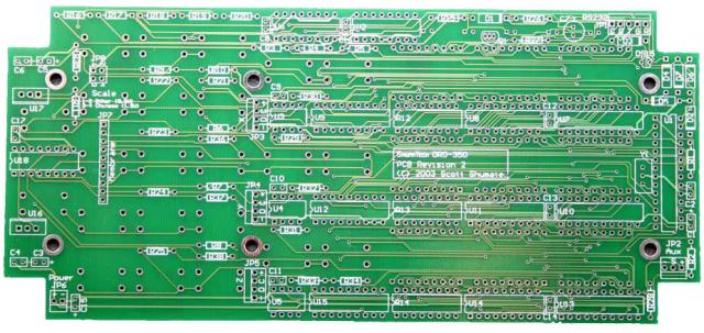
This is where we will take the bare DRO-350 PCB:
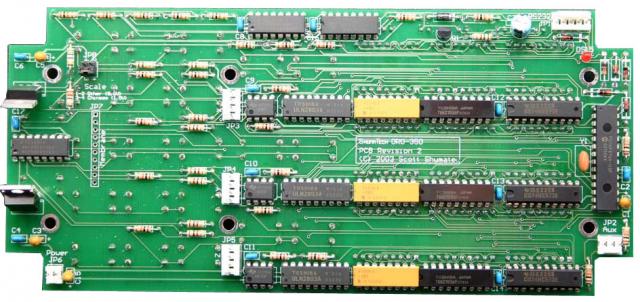
And turn it into a fully assembled board that looks like this:
First, you will need a DRO-350 PCB which you can buy from one of several vendors or if you know how, you can make one yourself from the PCB files. You will also need to acquire the electronics components listed on the bill of materials. You can get order the components yourself from the listed electronics distributors or you can by a kit from a vendor that includes everything. Before we get started, let's review a few things about electronics assembly.
Static Protection
Several of the ICs in the DRO-350 are static sensitive. The 74 series chips used in the DRO-350 are the HC variety, which stands for high-speed CMOS. HC devices have static protection on their pins but are still more static sensitive than the old TTL devices which were very hard to destroy. If possible, you should build the PCB on a static safe workspace that has a static mat. If this is not available, you should at least work on a non-carpeted area and wear a static strap at all times. Avoid handling the ICs any more than necessary and keep them in their static safe packaging until they are ready to install.
Soldering
A few quick words on soldering. Soldering is about applying the right amount of heat and solder to lock a mechanical connection in place. What this means is you don't want solder to be the electrical conductor. Instead you want a mechanical connection to be the point of electrical conduction.
A good solder joint has a nice, even flow and is shiny and smooth. If a solder joint is grainy or dull appearing, it is not a good joint and may crack or break in the future. Choose a solder iron that is appropriate for the task at hand, too little power and you will either be forced to heat the joint longer than is safe or you will not have enough heat to allow the solder to flow well, too much power and you risk heat stressing the component. For DIP soldering PCBs, a 25-30W iron is probably about right. A temperature controlled iron is even better but I suspect not many people attempting this project will have access to one.
When soldering on the PCB, put the tip of the solder iron on the pad and the pin at the same time. Apply the solder roughly at the point where the pin, pad, and solder iron tip meet. Quickly feed the solder until a small puddle extends to the edge of the pad and immediately stop. You don't want the tip of the iron on the pin and pad for more than 2-3 seconds. If you don't have much experience soldering, I would strongly suggest practicing a bit before starting on the PCB. Don't get discouraged, it just takes a bit of practice.