Table of Contents
PCB
Internal
Version
Dongle
Version
Quadrature
Cables
DRO-350
Installation
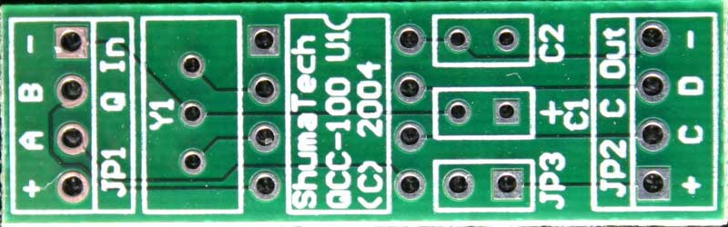
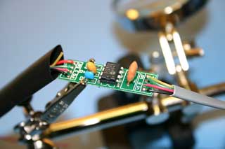
This section describes how to build up the QCC-100 printed circuit
board (PCB). The bare PCB is available for purchase on the
order page.
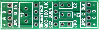
Bare QCC-100 PCB (Click for larger version - 37KB)
Common Construction Steps
|
|
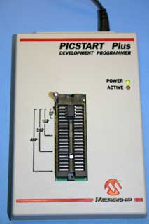
Step 1. Program the PIC
The PIC12F629 is programmed before installation into the PCB. There
are several programmers available to do this job. The
programmer pictured on the left is the PICStart Plus
available from Microchip, the manufacturer of the PIC.
There are several low cost programmers available
under $20 such as the JDM
or the El
Cheapo. Spark
Fun is a good place to get a low cost JDM programmer.
Use the HEX file available on the software
page to program the PIC with the programmer and
its associated software. Make sure the software
verifies the programming before proceeding with construction.
|
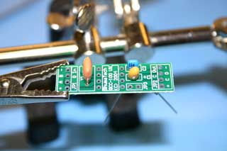 |
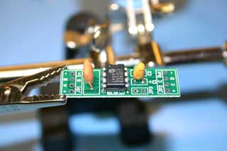
Step 2. Install the capacitors and resonator
Capacitor C1 is a 10uF tantalum capacitor and is polarized. The
capcitor will have a bar or + mark above the lead that
is positive. Install the capcitor so the positive
lead is in the hole in the PCB that has a + mark next
to it. Spread the legs apart on the solder side
so that it does not fall out during soldering.
Capacitor C2 is a 0.1uF ceramic capacitor and does
not have polarity. Install it in either orientation
and spread its legs apart on the solder side.
The ceramic resonator Y1 also does not have polarity
and can be installed in either orientation. Tack
solder one of the legs from the component side so that
it does no fall out.
Flip the PCB over to the solder side and solder all
of the leads to the PCB. Clip the leads with diagnoal
cutter as close to the solder as possible but be careful
not to damage or crack the solder joint.
|
 |
Step 3. Install the PIC
Insert the PIC into the PCB with the notch in the package matching the notch
shown on the PCB silkscreen. Tack solder one lead to
prevent it from falling out. Flip the PCB over
and solder the rest of the leads. |
From this point, you can make either version of the QCC-100,
either internal or dongle. Follow one of the following sets
of construction steps to build the desired version.
|
|
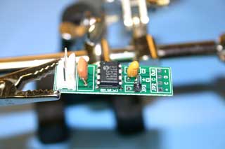
Step 4a. Install the MTA header
Insert the 4 pin MTA header into the PCB at position JP1. Solder
the pins from underneath the PCB.
|
 |
Step 5a. Solder the wires to the PCB
Solder four wires to the PCB. The wires should be cut to
5-6 inches (125-150 mm) in length.
|
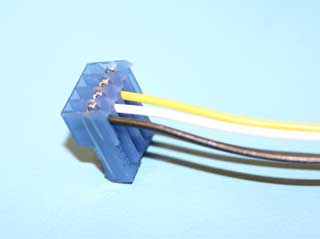 |
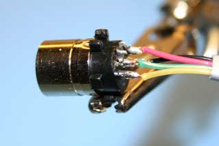
Step 6a. Attach the MTA receptacle
Attach the wire from the negative pad (black in the picture) on the
PCB to left-most position on the MTA connector when
the wires are oriented downwards. Attach the wire
from the D pad (white in the picture) next followed
by the wire from the C pad (yellow in the picture).
NOTE: If all three axes on the DRO-350 have QCC-100's
attached, you have the option to attach the wire
from the positive pad (red in the picture) to the last
position of the MTA connector and skip the next two
steps. If you do this, then move the jumper across
pins 3-4 on JP8 to pins 1-2. This will provide
the 5V that the QCC-100 needs to operate over the positive
wire on the MTA connector.
|
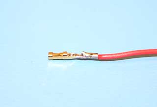 |
Step 7a. Crimp the terminal
Strip the end of the wire from the positive pad (red in the picture) and
attach it to the crimp terminal. This is most
easily done by soldering the stripped wire to the terminal
and then folding over the crimp tabs with needle-nose
pliers. |
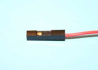 |
Step 8a. Install the housing
Slip the housing over the finished terminal paying attention to the
small tab on the terminal that locks it in place. This
tab is installed into the housing on the same side
as the hole it engages into on the housing. |
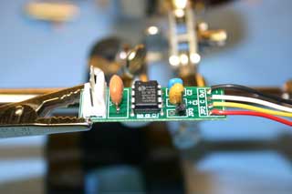
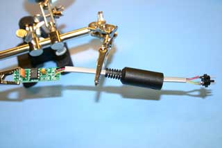
The finished internal version
will look like the following picture.
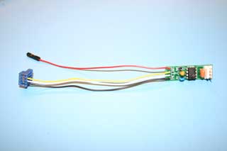
Completed Internal Version of the QCC-100
|
|
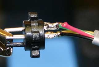
Step 4a. Attach the male mini-DIN connector
Strip the end of the wires from a four wire cable. A
telephone cable, as shown in the picture, works well.
Solder the wires to the four pin male mini-DIN
connector. The cable should be cut to
5-6 inches (125-150 mm) in length. Looking at
the mini-DIN connector from the wire side, the following
graphic shows the solder connections with the wire colors
as shown in the photo at left.
Male Mini-DIN Connector Viewed
from the Wire Side
|
 |
Step 5a. Solder the wires to the PCB
Before soldering the wires to the PCB, slide the mini-DIN cover
over the cable. Attach the wires to their
respective pads as shown in the previous step.
|
 |
Step 6a. Attach the female mini-DIN connector
Strip the end of the wires from a four wire cable. Solder
the wires to the four pin female mini-DIN connector. The
cable should be cut to 5-6 inches (125-150 mm)
in length. Looking at the mini-DIN connector from
the wire side, the following graphic shows the solder
connections with the wire colors as shown in the photo
at left.
Female Mini-DIN Connector Viewed
from the Wire Side
|
 |
Step 7a. Solder the wires to the PCB
Before soldering the wires to the PCB, slide the mini-DIN cover
and the heat-shrink tubing over the cable. The
positive wire (yellow in the picture) should not be
connected to the pad on the PCB. Attach the other
three wires to their respective pads as shown in
the previous step. Solder a separate wire to the
positive pad on the PCB and cut it to 5-6 inches (125-150
mm) in length.
NOTE: If all three axes on the DRO-350 have QCC-100's
attached, you have the option to attach the positive
wire on the cable (yellow in the picture) to the
positive pad on the PCB and skip the next step. If
you do this, then move the jumper across pins 3-4 on
JP8 to pins 1-2. This will provide the 5V that
the QCC-100 needs to operate over the positive wire
on the mini-DIN connector.
|
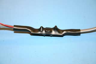 |
Step 8a. Apply the heat-shrink tubing
Use a heat gun or high wattage hair drier to shrink the heat-shrink tubing
over the PCB with the cables sticking out of both ends. |
The finished dongle
version will look like the following picture.
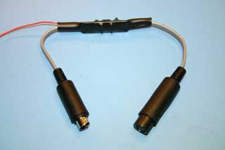
Completed Dongle Version of the QCC-100
The pin-out of the female mini-DIN connector as seen looking
into the connector is shown in the following graphic. Any
connector can be used to better match your particular quadrature
encoder. The mini-DIN connector is simply a convenient connector
and is already used for the Chinese cables on the DRO-350.
Pin-out Looking Into the Female Mini-DIN Connector
The internal version is installed inside the DRO-350 enclosure.
First, open the back of the DRO-350 by removing the four screws
in the corners. Remove the PCB from the back of the enclosure
by removing the six screws attached to the hex standoffs.
Unplug the MTA receptacle attached to the PCB
for the axis you want to install the QCC-100 on. Plug this
MTA receptacle into the QCC-100 MTA header. Plug the
QCC-100 MTA receptacle onto the MTA header on the DRO-350 that you
just disconnected.
Plug the QCC-100 power connector onto pin 1
of the JP8 header. It is probably a good idea to drop a small
amount of hot glue or some other adhesive on the joint between the
power connector and the JP8 header so that the power connector
does not come unconnected. If you install an additional QCC-100,
then daisy-chain its power connector to the one pin JP3 header on
the QCC-100 that is already installed.
The QCC-100 can be attached to the back of the enclosure
with hot glue or some souble-sided tape. This will prevent
the QCC-100 from moving around and possibly shorting something out.
|