OpenDRO User's Guide
5.4 Define Menu
Note that the define menu is displayed on screen as "dEFINE". The on-screen display for each menu item is shown underneath the menu name.
| Item | Machine | Description |
|
Tool Offset "tooL" |
Mill |
This function defines a tool offset for cutting edge compensation. The tool offsets are defined in terms of the tool diameter and the Z axis offset. The first screen will prompt you to enter the tool offset number with the numeric keypad. After pressing the number, you are prompted to enter the tool diameter. When entering the offsets, press the ENTER key to complete the offset or the CLEAR to make corrections or exit. Next, you will be prompted to enter the Z offset. After entering the Z offset, the tool offset is stored in the DRO. |
|
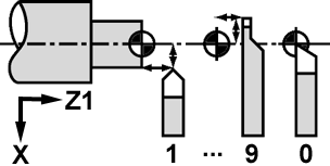
Tool Offset "tooL" |
Lathe |
This function defines a tool offsets for lathe operations. The tool offsets are defined as offsets of the X and Z1 axes. The following figure shows a visual representation.
The first screen will prompt you to enter the tool offset number with the numeric keypad. After pressing the number, you will be prompted to enter the X offset. When entering the offsets, press the ENTER key to complete the offset or the CLEAR key to make corrections or exit. Next, you will be prompted to enter the Z1 offset. After entering the Z1 offset, the tool offset is stored in the DRO. |
|
Bolthole "boLtho" |
Mill |
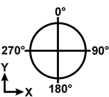
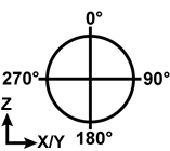
This function defines a new bolthole pattern for use with a mill. When this function is selected, the first screen will prompt you for the number of the bolthole memory position. Memory positions allow the specification of multiple sets of bolthole patterns and are recalled when the bolthole function is used. Enter the memory position number and press the ENTER key. Next, you are prompted to enter the total number of holes in the bolthole pattern. Enter the number and press the ENTER key. After entering the number of holes, the next prompt will be for the radius of the bolthole circle. Enter the radius and press the ENTER key. Next, the starting and ending angles of the bolthole circle are entered. The angles are entered in degrees and with respect to the following diagram when looking at the bolt-hole circle from the top:
The valid angle ranges are from 0.0 to 359.9 degrees. If the same angle is entered for both the starting and ending angles, a full circle bolt-hole pattern is created. Press the ENTER key to enter each angle. After entering the end angle, the bolt-hole pattern is stored in the DRO at the given memory position. |
|
Grid "GrId" |
Mill |
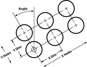
The grid function is used to define a series of equally spaced points along the X and Y axes that are oriented on an angle. When this function is selected, the first screen will prompt you for the number of the grid memory position. Memory positions allow the specification of multiple sets of grid points and are recalled when the grid function is used. Enter the memory position number and press the ENTER key. The diagram below shows the parameters that define a grid. Upon executing this function, you are prompted for each parameter. Enter the desired value via the numeric keypad and press the ENTER key to proceed on to the next parameter until all of them are defined.
The angle of the grid is centered on the lower left hole and is expressed in terms of the angular directions in the diagram below.
|
|
Radius "rAdIUS" |
Mill |
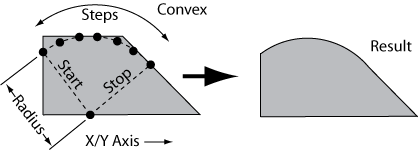
The radius function is used to define a convex or concave radius that is cut step by step. When this function is selected, the first screen will prompt you for the number of the radius memory position. Memory positions allow the specification of multiple sets of radii and are recalled when the radius function is used. Enter the memory position number and press the ENTER key. There are a number of parameters that define how the radius is cut. Each of the parameters are summarized in the figure below and described in more detail in the text that follows.
The first parameter to enter is the radius length. This defines the size of the arc for the cut. Enter the radius via the numeric keypad and press the ENTER key. For all parameters, press the ENTER key to confirm and move on to the next parameter. The second parameter is the radius shape, either concave or convex. A convex radius bulges out from its center point while a concave radius bulges in. Press the Z PRESET key to toggle between the two shapes. The next parameter is the second axis of the radius and defines the plane of the radius. The first axis is implicitly always the Z axis. If the X axis is selected, then stepping for the radius will proceed on the X and Z axes with the direction of the cuts occurring on the Y axis direction (front and back). If the Y axis is selected, then stepping for the radius will proceed on the Y and Z axes with the direction of the cuts occurring on the X axis direction (left and right). Press the Z PRESET key to toggle between the two axes.
The steps parameter is next and defines the number of steps to cut along the radius. The more steps the smoother the radius but also the more cutting operations that you must perform. Enter the desired number between 2 and 99.
The ending angle is the next parameter and it defines the stopping point on the radius. The radius cut always proceeds in a clockwise direction beginning at the starting angle so the ending angle must be in a clockwise direction from the starting angle and also be in the correct angular hemisphere. For example, for a convex radius with a starting angle of 0 degrees, 270 degrees is an invalid ending angle since it is counter-clockwise from the starting angle in the top angular hemisphere. |