OpenDRO User's Guide
5.2 Position Menu
Note that the position menu is displayed on screen as "PoSitN". The on-screen display for each menu item is shown underneath the menu name.
| Item | Machine | Description |
|
Tool Offset |
Mill |
This function selects one of the defined tool offsets. The DRO prompts you to select a tool offset number with the numeric keypad. Tool offset 0 is a special number that applies a tool with no offsets and is effectively used to turn off tool offsets. After selecting the tool offset, use the numeric keypad to select the cutting edge to compensate for. The edge positions are selected according to the following keypad pattern.
When an axis position is compensated due to an edge position selection, the left-most decimal point in the display for that axis is turned on. |
|
Tool Offset "tooL" |
Lathe | This function selects one of the defined tool offsets. The DRO prompts you to select a tool offset number with the numeric keypad. Tool offset 0 is a special number that applies a tool with no offsets and is effectively used to turn off tool offsets. |
|
Centerline "C-LINE" |
Mill |
Centerlines are meant to quickly find center points in lines and circles. The centerline function sets a zero at the half way point between the current zero and current position for an axis. If the scale is in incremental mode, the zero will be an incremental zero. Vice versa, if in absolute mode, the zero will be an absolute zero. Set a centerline zero by first moving to the desired position. Switch to incremental or absolute mode with the ABS/INCR key for the desired zero type. Select the centerline menu item and the DRO will display a prompt to press the preset key for the axis the zero is desired on. |
|
Diameter "dIA" |
Lathe |
Diameter mode doubles an axis dimension to show the diameter of a work piece instead of its radius. The left-most decimal point in the axis display is turned on to indicate that the DRO is in diameter mode. When this operation is selected, the DRO will prompt you to select the axis to apply the diameter to. Selecting this operation when diameter mode is already active will clear it. |
|
Compound Angle "CoMPN" |
Lathe |
This function sets the angle of the compound for use when vectoring the compound (Z2 axis) movement into the cross-slide (X axis) and carriage (Z1 axis). Positive angles indicate that the compound is positioned clockwise from the center position and negative angles indicate that the compound is positioned counter-clockwise.
Enter the angle from positive to negative 99.9 degrees with the numeric keypad and press the ENTER key to accept the angle. Press the CLEAR to make corrections or exit without setting the angle. |
|
Bolthole "boLtho" |
Mill |
This function uses the defined bolt-hole pattern to set X and Y axis incremental zeros at each bolt-hole position in the pattern. The center of the bolt-hole pattern is the incremental zeros of the X and Y axes when the function is started so before starting this function, set X and Y incremental zeros at the center of the bolt-hole pattern. A "hole 1" prompt is displayed when this function is initiated. This indicates that an incremental zero is about to be set for the first bolt-hole. Press the ENTER key and the DRO switches to displaying the axis positions so that you can move the X and Y axes to zero for the first bolt-hole. Press the ENTER key again and continue through the bolt-hole pattern. After the incremental zero is set for the last bolt-hole, press ENTER to exit out of the bolt-hole pattern use function. The incremental zeros for the X and Y axis are restored to the values that were defined for the center of the bolt-hole pattern. If you make a mistake, you can go backward through the screens at any time with the CLEAR key. |
|
Grid "GrId" |
Mill |
This function uses the defined grid pattern to set X and Y axis incremental zeros at each grid hole in the pattern. The center of the first hole in the grid pattern is the incremental zero of the X and Y axes when the function is started. Before starting this function, set X and Y incremental zeros at the center of the first grid hole. A "hole 1" prompt is displayed when this function is initiated. This indicates that an incremental zero is about to be set for the first grid hole. Press the ENTER key and the DRO switches to displaying the axis positions so that you can move the X and Y axes to zero for the first hole. Press the ENTER key again and continue through the grid hole pattern. After the incremental zero is set for the last grid hole, press ENTER to exit out of the grid use function. The incremental zeros for the X and Y axis are restored to the values that were defined for the first hole in the grid pattern. If you make a mistake, you can go backward through the screens at any time with the CLEAR key. |
|
Radius "rAdIUS" |
Mill |
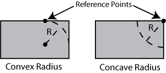
The radius function is used to cut a convex or concave radius into a work piece by progressing through the cut in a series of small steps. See the description of the radius function in the define menu section below for more detail on the parameters that define the radius. The reference point for the radius is taken from the incremental zeros for the two axes in the plane of the radius, either X and Z or Y and Z. The reference point is defined as the center point of the radius for a concave radius or the point on the radius directly above the center point for a convex radius. You must define the incremental zeros that define the reference point before starting the function. The figure below shows the location of the reference points for both convex and concave radii.
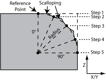
Before starting the function, select the tool that you want to use for the cut. The tool must be a ball nose cutter and the diameter and Z offset must be correctly defined for the tool. If you initiate the radius function without a tool selected, it will display a message and cancel the function. A "step 1" prompt is displayed when this function is initiated. This indicates that incremental zeros are about to be set for the first step cut. Press the ENTER key and the DRO switches to displaying the axis positions so that you can move the Z and X/Y axes to their zeros for the first step. After reaching the zero points, you can lock those axes and begin the cut. The cut is made by moving the third axis, either X or Y, that is perpendicular to the plane of the radius. When finished with the current cut, press the ENTER key again and proceed through the rest of the cuts. After incremental zeros are set for the last step, press ENTER to exit out of the radius function. The previous incremental zeros for the X, Y, and Z axes are restored to the values that were defined before starting the radius function. Also, the cutting edge compensation is reset to the previous setting. If you make a mistake, you can go backward through the screens at any time with the CLEAR key. An example of a finished radius cut is shown below. In this example, the radius is convex, has a start angle of 0 degrees, has an end angle of 90 degrees, and is defined for 5 steps. Notice the circular cuts from the ball nose cutter are tangent to the radius at each step point but arc out from that point leaving excess material. This is called scalloping and can give the radius a non-smooth finish. To reduce scalloping, define the radius with more steps and/or use a larger diameter ball nose cutter.
|
|
Workspace "WSPAC" |
Both |
Workspaces, sometimes known as sub-datums, are incremental and absolute zero points defined in addition to the primary zero points. When you switch to a new workspace, the current zeros are saved and the zeros for the new workspace are used instead. You can switch around between all of the workspaces and the zero points for each workspace are permanently saved. Zeros for the other workspaces are established just like they are with the primary zeros using the ZERO and PRESET keys. Workspaces are useful when switching between multiple parts or when working on a drawing that establishes a new datum and using an incremental zero is not convenient or possible. |