DRO-350 PCB Construction
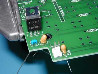 |
Step 1. Build the 5 Volt Power SupplyThe 5 volt power supply consists of device U16 and capacitors C3, C4, and C15. An optional MTA-100 connector can also be used for the power entry connector JP6. Pay special attention paid to the polarity of C15 and C3. These are tantalum capacitors and have a marking on the POSITIVE lead. Make sure to insert the marked lead to the side marked with a + on the PCB. Also notice that the pad this lead is inserted into is square instead of round. First, insert the capacitors C3, C4, and C15 into their respective positions and bend their leads apart at about a 45 degree angle. Next insert U16 and solder one pin from the component side to hold it in place. Flip the PCB over to the display side and solder all of the unsoldered leads. Use diagonal cutters to clip all of the leads. Install the optional 2 pin MTA-100 jumper in JP6. To solder the jumper in place, put a small pool of solder on one of the pads. While holding the jumper in one hand, heat the pool of solder with the iron and quickly insert the jumper. Finish soldering after flipping the board to the display side. Test the 5V supply by probing with a voltmeter. Temporarily connect the 9V external power supply to JP6. Make sure the correct polarity is observed as shown on the PCB silk screen. The Aux connector JP2 is a convenient place to probe between the + and - pads. The voltmeter should indicate 5.0V ±0.2V. |