DRO-350 PCB Construction
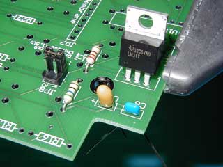 |
Step 2. Build the 1.5 Volt Scale Power SupplyThe 1.5 volt power supply is what powers the Chinese scales and consists of device U17, capacitors C5 and C6, and resistors R11 and R35. Again, pay special attention paid to the polarity of C5. Observe the same capacitor polarity markings as described in step 1. First, insert the resistors R11 and R35 into their respective positions and solder them in place from the component side of the PCB. Next, insert the capacitors C5 and C6 and bend the leads apart. Insert U17 and solder one pin from the component side to hold it in place. Flip the PCB over to the display side and solder all of the unsoldered leads. Use diagonal cutters to clip all of the leads. With the 9V external power supply connected, test the 1.5V supply by probing with a voltmeter between pad 3 on JP8 and the - pad on JP3. The voltmeter should register 1.5V ±0.06V. If you plan to use Chinese scales, then either solder a 100 mil, four pin header in JP8 or install a jumper wire between pads 3 and 4 on JP8. To solder the header in place, put a small pool of solder on one of the pads. While holding the header in one hand, heat the pool of solder with the iron and quickly insert the header. Finish soldering after flipping the board to the display side. |