DRO-350 PCB Construction
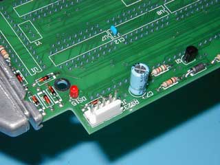 |
Step 5. Build the PIC ProgrammerBuild the serial programming circuit around the PIC and also install the ceramic resonator. Begin by installing diodes D1-D7 with the correct orientation of the anode and cathode. The cathode is indicated on the PCB by a white bar on the silkscreen and a square pad instead of a round pad. The cathode-side of the diode itself is usually marked with a bar or solid colored area. The diodes are mounted on 400 mil centers like the resistors so a lead forming tool would be handy here too. Be very, very careful that the correct diode part number from the BOM is installed in the correct designator on the PCB. Bad things could happen if not. Solder the diodes from the component side of the PCB. Insert the transistor Q1 with the correct orientation as noted on the PCB. The transistor will have a flat side that is installed in the same position as the flat side on the silkscreen. Bend the outer leads of the transistor outward to hold it in place but do not solder it yet. Insert the T1-size (3mm) LED with designator DS15. The important thing to note about the LED is that the cathode is the shorter lead and MUST be installed in the square pad on the PCB. The round pad is for the anode, which is the longer lead. After inserting the LED, bend the leads apart to hold it in place but do not solder it yet. If installing the optional light pipe indicated on the BOM, then the height of the LED should be as low as possible. Otherwise, the height is not at all critical. Install the electrolytic capacitor C7 next. Note that electrolytic capacitors are polarized like tantalum capacitors. Pay careful attention to the markings on the electrolytic because the negative lead is usually marked on an electrolytic where as the positive lead is usually marked on a tantalum. Install the electrolytic capacitor with the negative lead in the pin opposite the positive pad marked on the PCB. Again, bend the leads apart to keep it in place but do not solder. Now, flip the board to the display side and solder the leads for Q1, DS15, and C7. Install the optional 5 pin MTA-100 jumper in JP1. To solder the jumper in place, put a small pool of solder on one of the pads. While holding the jumper in one hand, heat the pool of solder with the iron and quickly insert the jumper. Finish soldering after flipping the board to the display side. |