DRO-350 PCB Construction
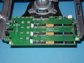 |
Step 6. Install the ICs and Resistor PacksInstall the ICs next but be careful not to force them into the PCB. If the pins do not line up, gently bend them by pressing the side of the IC on a hard surface with a static safe bag between the pins and the surface. Insert the ICs with designators U1-U15 and U18 and also the resistor packs R12-R14. To solder the ICs and resistor packs, carefully solder one pin on each from the component side. This serves to hold it in place so you can solder the rest of the pins from the display side. After soldering one pin on each, flip the board and solder the rest of the pins. Be careful not to start soldering with the one pin you soldered before otherwise it might fall out. Lastly, install the 20MHz ceramic resonator Y1. The resonator does not have an observed polarity so it can be installed in any orientation. Carefully solder one of the leads of the resonator to the PCB to hold it in place and then finish soldering the other leads from the display side. Install the optional 3 pin MTA-100 jumper in JP2 and the optional 4 pin MTA-100 jumpers in JP3-JP5. To solder a jumper in place, put a small pool of solder on one of the pads. While holding the jumper in one hand, heat the pool of solder with the iron and quickly insert the jumper. Finish soldering after flipping the board to the display side. |